
Resistor Selection Guides
Resistor Videos
What is a Resistor?
The resistor is the most common and well-known of the passive electrical components. A resistor resists or limits the flow of electric current in a circuit. There are many uses for resistors: they are used to drop voltage, limit current, attenuate signals, act as heaters, act as fuses, furnish electrical loads and divide voltages.

What is Ohm's Law?
Ohm’s law is a simple equation that shows the relationship between resistance, voltage and current through a metal wire, or some other type of resistive material. In mathematical terms, Ohm’s law is written as:
I = V/R
where I is the current (amps), V is the voltage, and R is the resistance.
Ohm’s law can also show the relationship between resistance, voltage and power using the following equation:
P = (V*V)/R
where P is the power (watts), V is the voltage, and R is the resistance.

Types of Resistors
Fixed Resistors
A fixed resistor is one in which the value of its resistance cannot change.
Variable Resistors
A variable resistor is a resistor whose value can be adjusted by turning a shaft or sliding a control. They are also called potentiometers or rheostats and allow the resistance of the device to be altered by hand.
Non-Linear Resistors
A non-linear resistor is a resistor that has resistances that vary significantly with applied voltage, temperature or light. Types of non-linear resistors are varistors, thermistors and photoresistors.
Common Resistor Terminology
Critical Resistance Value
The maximum nominal resistance value at which the rated power can be loaded without exceeding the maximum working voltage. The rated voltage is equal to the maximum working voltage in the critical resistance value.
De-rating Curve
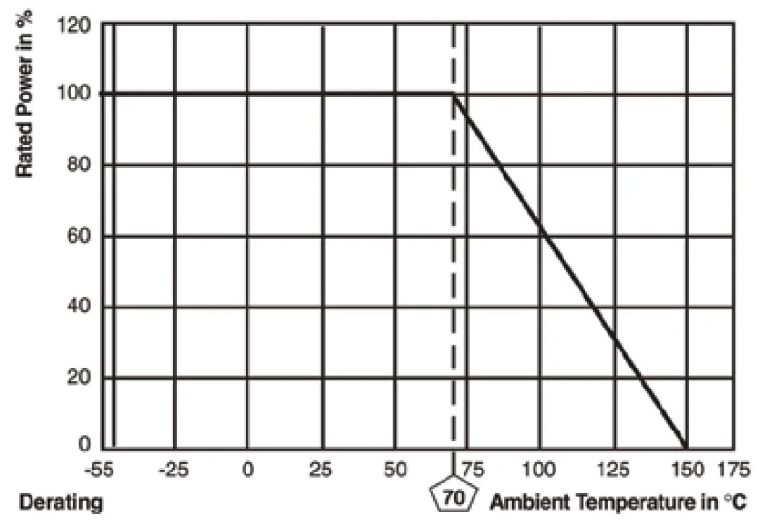
The curve that expresses the relation between the ambient temperature and the maximum value of continuously loadable power at its temperature, which is generally expressed as a percentage.
Dielectric Withstanding Voltage
The rated voltage that can be applied to a designated point between the resistive element and the outer coating, or the resistive element and the mounting surface, without causing dielectric breakdown.
Electrostatic Discharge (ESD) Sensitivity
In resistors, ESD sensitivity is a function of their size. The smaller the resistor, the less space there is to spread the energy pulsed through it from the ESD. This energy concentration in a small area of a resistor’s active element causes it to heat up, which could lead to irreversible damage. With the growing trend of miniaturization, electronic devices, including resistors, are becoming smaller and smaller, causing them to be more prone to ESD damage.
Load Life Stability
Load life stability is the characteristic most relied upon to demonstrate a resistor’s long-term reliability. Military testing requirements to 10,000 hours with limits on amount of shift and the resistors value and the number of failures results in a failure rate evaluation. (Please see the "Precision Current Sensing" under our "applications" section on this website for a complete explanation.
Maximum Overload Voltage
The maximum value of voltage capable of being applied to resistors for a short period of time in the overload test. Typically the applied voltage in the short time overload test is 2.5 times larger than the rated voltage. However, it should not exceed the maximum overload voltage.
Maximum Working Voltage (or Maximum Limiting Element Voltage)
The maximum value of DC voltage or AC voltage (rms) capable of being applied continuously to resistors or element. However, the maximum value of the applicable voltage is the rated voltage at the critical resistance value or lower.
Noise
Noise is an unwanted AC signal from within the resistor. Resistive noise can have a devastating effect on low-level signals, charge amplifiers, high gain amplifiers, and other applications sensitive to noise. The best approach is to use resistor types with low or minimal noise in applications that are sensitive to noise.
Power Rating
Power ratings are based on physical size, allowable change in resistance over life, thermal conductivity of materials, insulating and resistive materials, and ambient operating conditions. For best results, employ the largest physical size resistors at less than their maximum rated temperature and power.
Rated Ambient Temperature
The maximum ambient temperature at which resistors are capable of being used continuously with the prescribed rated power. The rated ambient temperature refers to the temperature around the resistors inside the equipment, not to the air temperature outside the equipment.
Rated Power
The maximum amount of power that can be continuously loaded to a resistor at a rated ambient temperature. Network and array products have both rated power per package as well as per element.
Rated Voltage
The maximum value of DC voltage or AC voltage (rms) capable of being applied continuously to resistors at the rated ambient temperature.
Reliability
Reliability is the probability that a resistor (or any other device) will perform its desired function. There are two ways of defining reliability. One is Mean Time Between Failures (MTBF) and the other is Failure Rate per 1000 hours of operation. Both of these means of evaluating reliability must be determined with a specific group of tests and a definition of what is the end of life for a device, such as a maximum change in resistance or a catastrophic failure (short or open). Various statistical studies are used to arrive at these failure rates and large samples are tested at the maximum rated temperature with rated load for up to 10 000 hours (24 hours per day for approximately 13 months). Reliability is generally higher at lower power levels.
High Speed and Response Time

Figure 1: The Equivalent circuit of a resistor